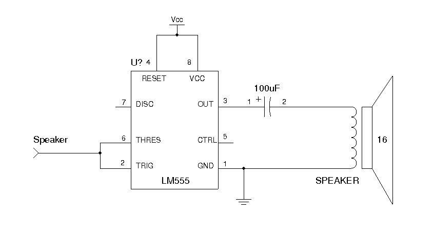

That causes the output of the lower comparator to go high, triggering the SET input on the RS flip-flop. The DIS and THRES nodes are at VCC when the trigger occurs, as is the non-inverting input of the the lower comparator. Image derived from public domain images ( waveform and circuit) by Wikipedia users InductiveLoad, JacksonMiss, and BlanchardJ).Ĭomparing the circuit diagram with the block diagram above, it's fairly easy to see what's happening. When a transition occurs on that input signal, the 555 circuit outputs a pulse of fixed length, regardless of the time between the triggering transition and the signal returning to its prior state.

In a monostable application, an input signal is monitored for transitions. We typically divide 555 applications into two groups: astable and monostable (bistable is also possible, but as that's just basically ignoring a lot of the circuitry to use only the flip-flop, it's uninteresting and I won't discuss it any more). Typically, the voltage(s) used for comparison come from one or more resistor/capacitor circuits the time required to charge (or discharge) the capacitor(s) determines how long the outputs remain high (or low). The basic concept is fairly simple: by looking at one or more analog voltages (with the comparators on pins THRES and TRIG), generate a digital signal on a buffered output pin, and the inverse of that signal on the open collector output pin. Unlike most early ICs, which typically had several copies of a single gate, it combines several different logical blocks into one package: two comparators, an S-R flip-flop, a buffer and an open-collector output.ĭiagram in public domain, courtesy Wikipedia user BlanchardJ It was introduced in 1971 commercial integrated circuits had only been on the market for about 10 years at that time. The 555 (or "triple nickel" as it's sometimes called) is one of the oldest integrated circuits around. If you are relatively new to electronics, having come to it through Arduino, Raspberry Pi, or robotics, you can easily be forgiven for not knowing exactly what a 555 timer is. Naturally, the first suggestion that popped up was "throw a 555 timer at the problem! Done!" I took issue with that, and I'm going to explain why here. It turns out, she was hoping to control a motor's speed using a pot, without an Arduino in the mix, to create a high-power, variable-value resistor out of the FET. 3, No.I recently had a brief Twitter dot com exchange wherein a less-experienced but still very capable "pro-am" electronics hobbyist was asking whether FETs could be driven directly by analog voltages.

Read more articles from the Ideas for Design Series: Vol. Michael Covington, PhD, operates a consulting practice, Covington Innovations (in Athens, Ga. The timer chip was changed to a bipolar NE555 (rated for 200-mA sink and source current), an 82-Ω resistor was added to guarantee that the current would always be below 150 mA, and the switching frequency was reduced to 3 kHz to reduce the proportion of time spent “on the slope.” The resulting circuit performed more reliably, and the MOSFET did not even get warm. Using the well-known current-charging equation I = C dV/dt, we find that the gate charging and discharging current with a 12-V square wave is about 21 mA, twice the rated output of the CMOS 555. The input capacitance of the IRF 4905 is typically 3500 pF. Much of the time, it was neither fully on nor fully off, but in the lossy intermediate-state switching-transition mode. That explained why the MOSFET was running hot. Pin 3 of the 555 was connected directly to the MOSFET gate.Įxamination with an oscilloscope showed that the gate voltage had a rise and fall time of about 2 µs and that the pulse-width modulation (PWM) switching frequency was about 100 kHz, so about 40% of each cycle was spent on the rise and fall. In addition, the MOSFET (an IRF 4905) ran hot. It originally used a CMOS TLC555, which kept failing with an open output pin as the failure mode. The figure shows part of a pulse-width-modulated dimmer for a 12-V incandescent lamp. This file type includes high resolution graphics and schematics when applicable. Newer CMOS versions such as the 7555, LMC555, and TLC555 use less power, but they have trouble sourcing enough current to drive a gate well and can even be damaged by load mismatch. The original bipolar 555 timer, the NE555, is excellent for driving a power MOSFET’s gate. This article is part of the Ideas for Design Series: Vol.


 0 kommentar(er)
